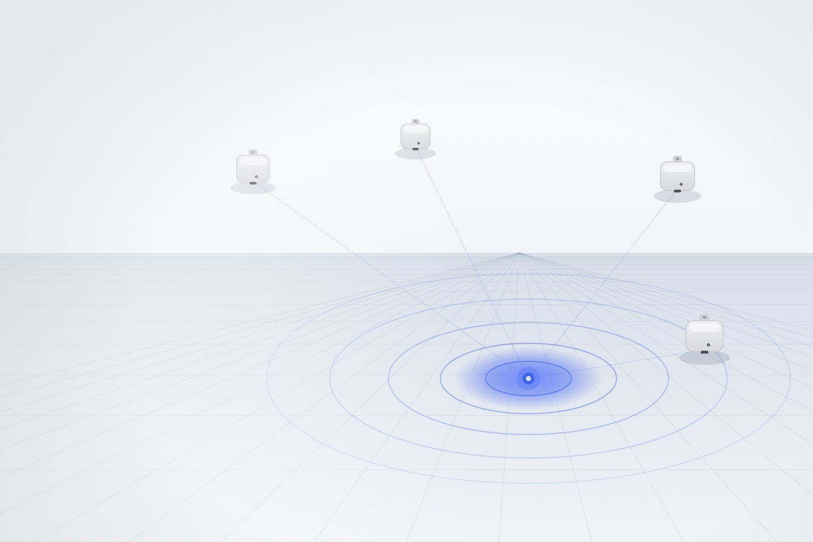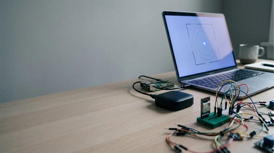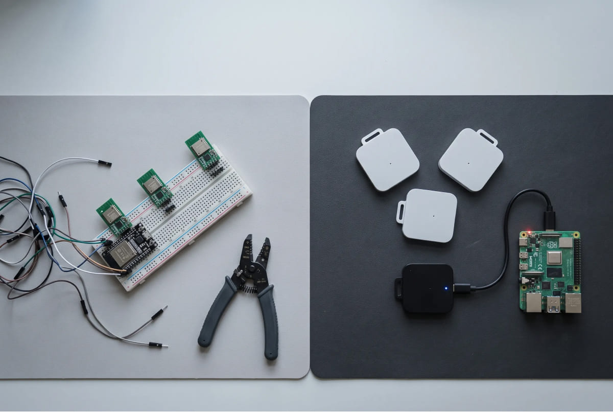
One UWB module costs almost nothing next to a full kit. So most developers who need indoor position data start there. They buy a few modules, wire them to an ESP32 or a Raspberry Pi, and flash an open-source library.
Range values show up within a day. The wall comes after that. Turning those ranges into X, Y coordinates drags in antenna delay calibration, filtering, and trilateration.
Short answer. Build it yourself if parts cost is your hard limit and your calendar is open. Buy a UWB dev kit if you need X, Y coordinates on your desk this week. Both paths reach centimeter-level indoor positioning. What differs is whether you pay in money or in time.
What is a UWB dev kit
A UWB dev kit is a test package with anchors and tags already matched to each other, so you can pull indoor coordinates the day it arrives. Parts and firmware ship tuned together.
If the radio side is new to you, start with our intro to UWB indoor positioning.
The GrowSpace Creator Kit holds three anchors, one developer tag, one listener, and three brackets. Build it yourself and you buy those same pieces separately, then start by flashing firmware onto each one.
What you need to build one
Three things. UWB modules, a board to read them, and open-source code to connect the two.
You buy several off-the-shelf UWB modules, wire each to a microcontroller or a single-board computer, and load a library that handles the radio. ESP32 nodes make a common starting point. Plenty of people go with Arduino or Raspberry Pi instead.
The sequence stays simple. Flash each module, mark some as anchors and one as a tag, then read range values over serial. Anchors sit fixed on the wall as reference points. The tag is whatever you want to locate.
This path has real strengths. It costs little, everything stays open, and every layer sits in plain view, so you learn UWB from the bottom. For a class project, a personal experiment, or a team that needs full firmware control, it makes sense.
That gets you range data. You still have no coordinates.
Why DIY UWB positioning gets harder than it looks
Because range is not position. Four separate problems sit in between.
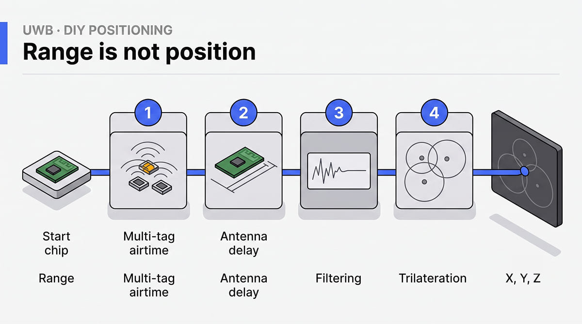
Multiple tags won’t run at once. The popular open-source libraries came out of demos. One tag behaves. Move two or three at the same time and the signals collide, because nothing in the library splits airtime to keep them apart. You write that layer yourself.
Antenna delay calibration. A raw module doesn’t read centimeters out of the box. Antenna delay varies from unit to unit, so ranges drift until you measure and correct each one. Skip it and a centimeter-grade sensor misses by tens of centimeters. The work is dull, it goes one device at a time, and mistakes slip in easily.
The numbers jump. Real rooms hold metal shelving, glass, and people walking through. Once signals start bouncing, clean range values wobble. To settle them you add filtering. A moving average at minimum, a Kalman filter to do it properly.
Turning range into coordinates. This one is the biggest. A module gives you distance to each anchor, nothing more. To fold three or four distances into a single X, Y, Z you hand-code trilateration. Then you handle bad anchor geometry, and debug why the point keeps drifting through a wall.
Taken one at a time they all look small. A day for calibration, half a day for filtering. Any decent engineer can solve each piece, which is exactly why DIY looks easy the night before you start. But they don’t arrive one at a time. The antenna delay you dialed in on Monday drifts the moment you add a third tag, and the filter you tuned in a quiet room falls apart when a forklift rolls past. The hours pile up quietly.
None of this makes DIY a bad call. It means the work doesn’t end when the parts arrive. You schedule it.
What a finished kit hands you
All four of those come solved.
You mount the anchors, enter each anchor coordinate once in millimeters, and plug in the listener. Position data starts flowing. No positioning server to stand up first, no firmware to flash.
The listener saves the most time early on. It plugs straight into a PC over USB and pushes coordinates out over serial, so you get live values without a gateway in the middle.
Trilateration, the big one, happens on the tag. Send lep to the developer tag and a string starting with POS, comes back, carrying X, Y, Z and a quality figure. No math to write.
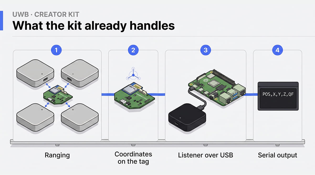
Getting data out stays open. Read the listener over serial (UART) and pipe it into Python, or add a gateway and subscribe over MQTT. Parsing a comma-separated string works in any language. Wiring diagrams and sample code for Arduino, Raspberry Pi, and ESP32 sit in the docs, so hooking up a board is closer to following a recipe than doing research.
Check one thing before you apply power. The left and right connectors on the developer tag run at different voltages. Left is 3.3V, right is 5V. Match the connector to your board’s logic level, not to its brand name. Arduino alone ships in both 5V and 3.3V families. Look up what your board runs at, then pick the side. Cross them and you damage the UART.
Kit specs put accuracy at 10 to 30 cm, with updates up to 10 Hz. Tracking several tags at once is standard behavior, and a gateway handles 15 of them at 10 Hz. At a large automotive logistics site in Korea, packed with new vehicles, a PoC measured 23.05 cm. That figure came from sensor fusion, UWB together with RTK-GPS and other inputs, not from the kit on its own. Keep the two apart. What they share is the positioning engine underneath, the same one running at more than 40 industrial sites.
Side by side
| Build it yourself | Finished UWB dev kit | |
|---|---|---|
| Upfront cost | Low, parts are cheap | One purchase |
| Time to first coordinate | Days to weeks | Same day |
| Skills needed | Firmware, signal filtering, coordinate geometry | Basic wiring, parsing a serial string |
| Multiple tags | You write the time-division layer | Built into firmware (15 at 10 Hz with a gateway) |
| Coordinate output | Range only, you do the math | Tag outputs POS,X,Y,Z,QF |
| Maintenance | All yours | Ships with tuned firmware |
| Best for | Learning UWB, tight budget, full control | Getting a working PoC out fast |
If you read one row, read time to first coordinate. Most of the others follow from it.
When a UWB dev kit pays for itself
When your time costs more than the kit does.
Ship a location feature on a deadline and the hours you sank into antenna delay calibration and trilateration debugging turn into the expensive choice. A researcher testing a hypothesis, a startup demoing to investors, a systems integrator scoping a pilot: all of them need coordinates today.
The reverse holds too. If learning is the point, or the budget truly won’t move, DIY earns its keep. You just have to be honest about which one you are.
FAQ
Not really. A finished kit runs on its own tuned firmware with matched anchors and tags. Treat it as a separate setup rather than an upgrade to loose modules.
The Creator Kit is a fixed indoor setup, and the hardware carries no water or dust rating. Range-wise it still works outside, with anchors up to 20 m apart and 25 m maximum. It isn’t built to live outdoors, though. Precise positioning across a large outdoor area belongs to GPS-RTK.
Yes, once you handle antenna delay calibration and filtering yourself. Range values from an uncalibrated module don’t deserve the word centimeter.
Start on your desk
Both roads end in the same place. If you have the time and want to learn every layer, build it. People who have wrestled with calibration and trilateration understand this technology far better. If you need coordinates by this afternoon, three anchors and a listener get you there faster.
→ To skip the calibration and filtering and go straight to coordinates, take a look at the Q1 Creator Kit.