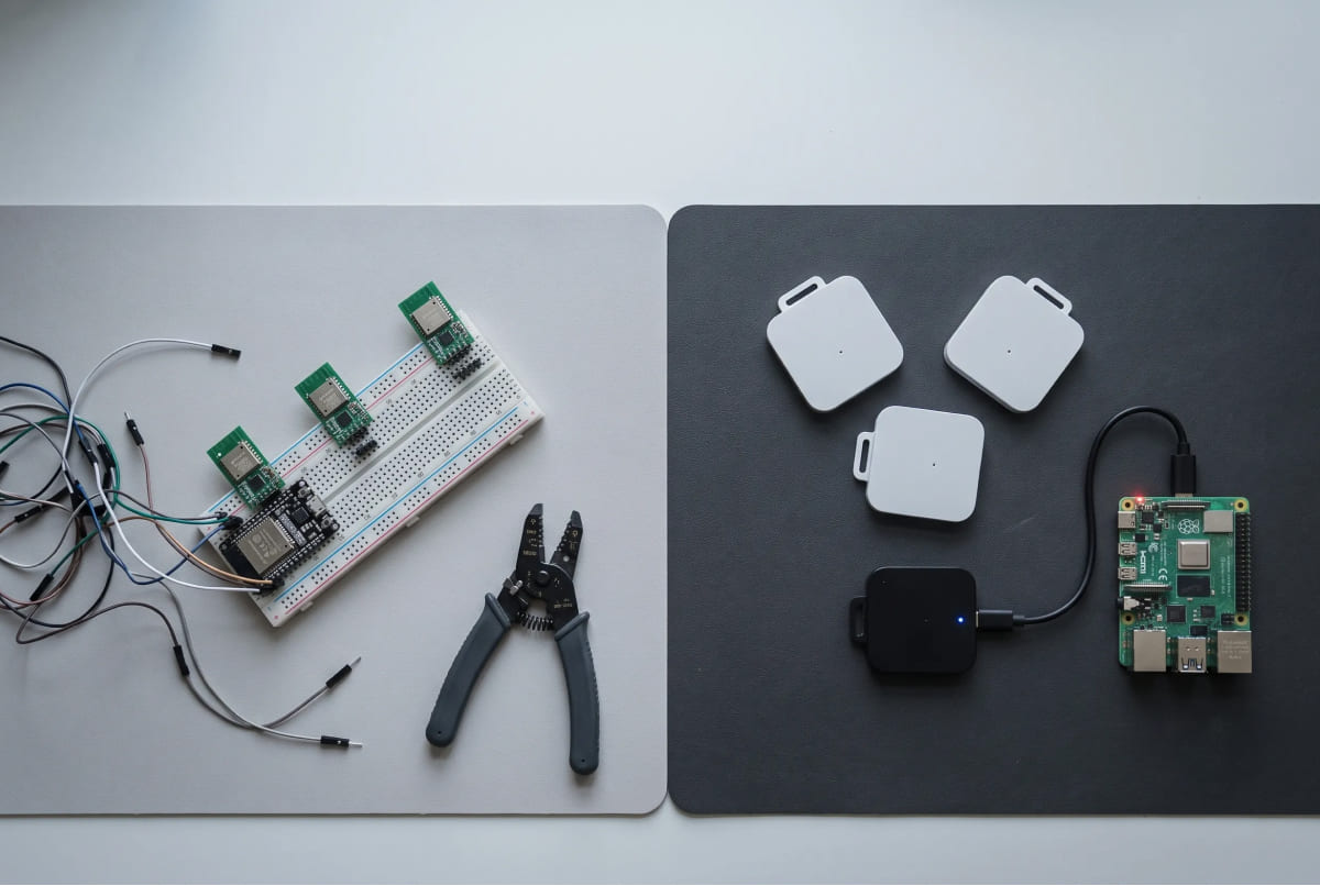
Most “uwb arduino” tutorials stop at distance. You wire up two off-the-shelf UWB modules,
run an open-source ranging library, and the serial monitor prints a number in meters.
Then you try to turn three of those distances into an actual point on the floor, and the whole thing falls apart.
That gap is the reason this guide exists.
Distance is not position. A range tells you how far a tag sits from one anchor. A position tells you
where the tag actually is: an X,Y coordinate you can plot, log, or feed to a robot.
Getting from one to the other means trilateration, anchor placement,
and antenna-delay calibration you handle yourself.
This post walks the honest DIY path first, then shows the shortcut for people who need coordinates today.
How do I get X,Y coordinates (not just distance) from UWB on Arduino?
Short answer: you need at least three anchors, a trilateration step, and calibrated antenna delays.
Distance alone gives you a circle, not a point.
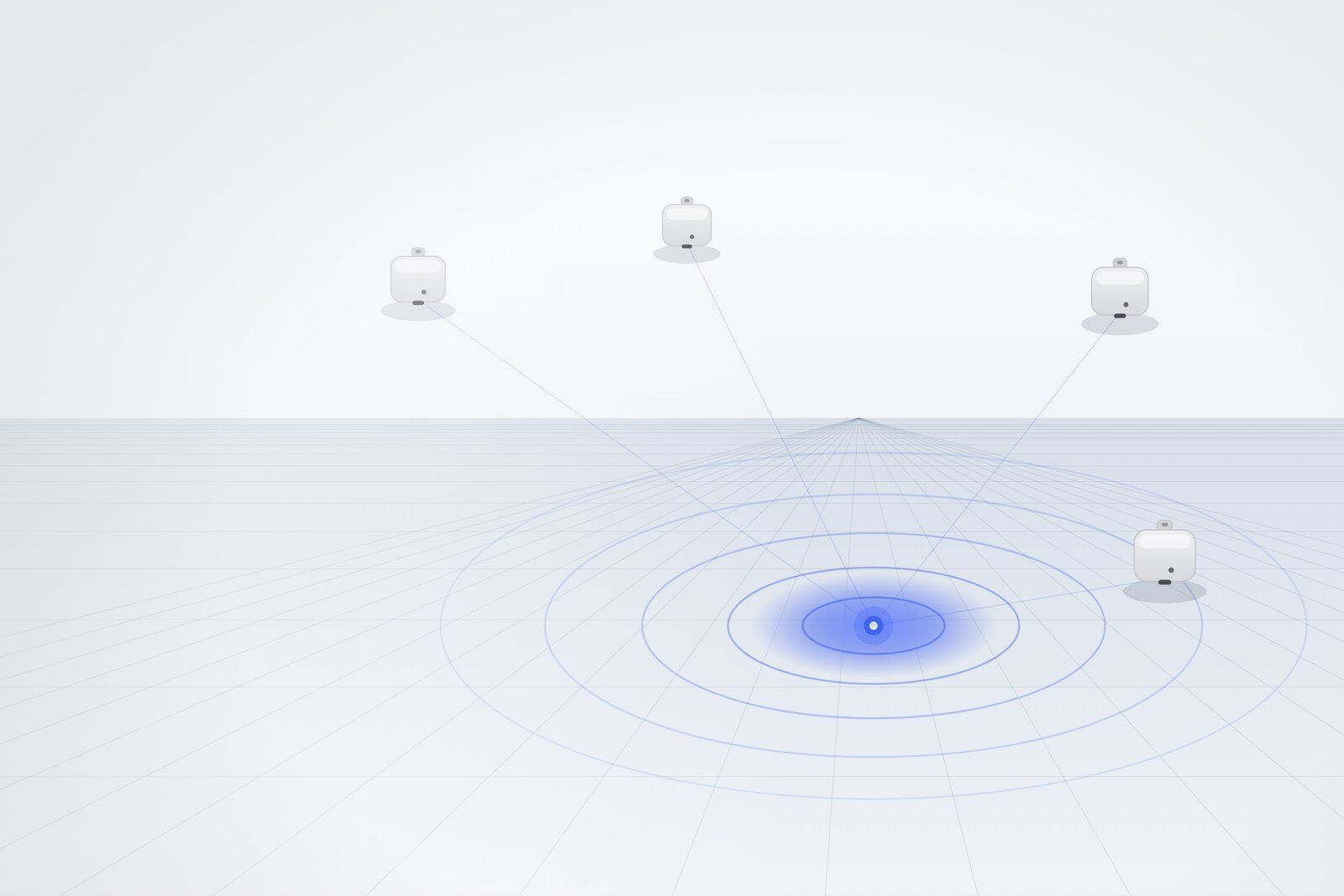
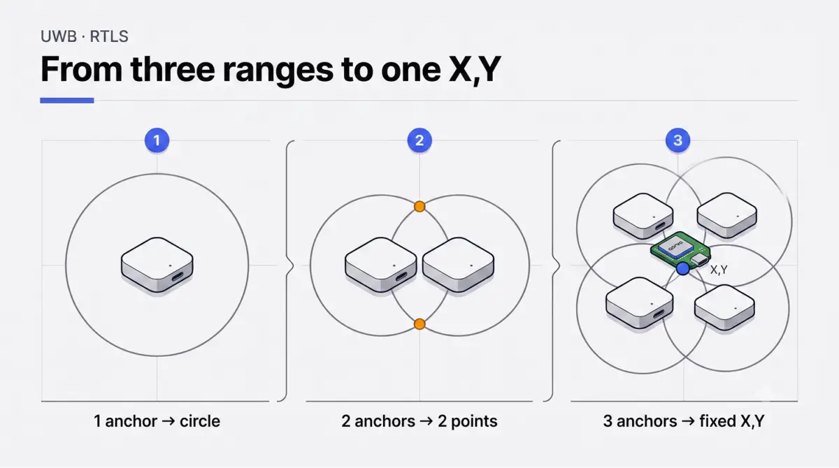
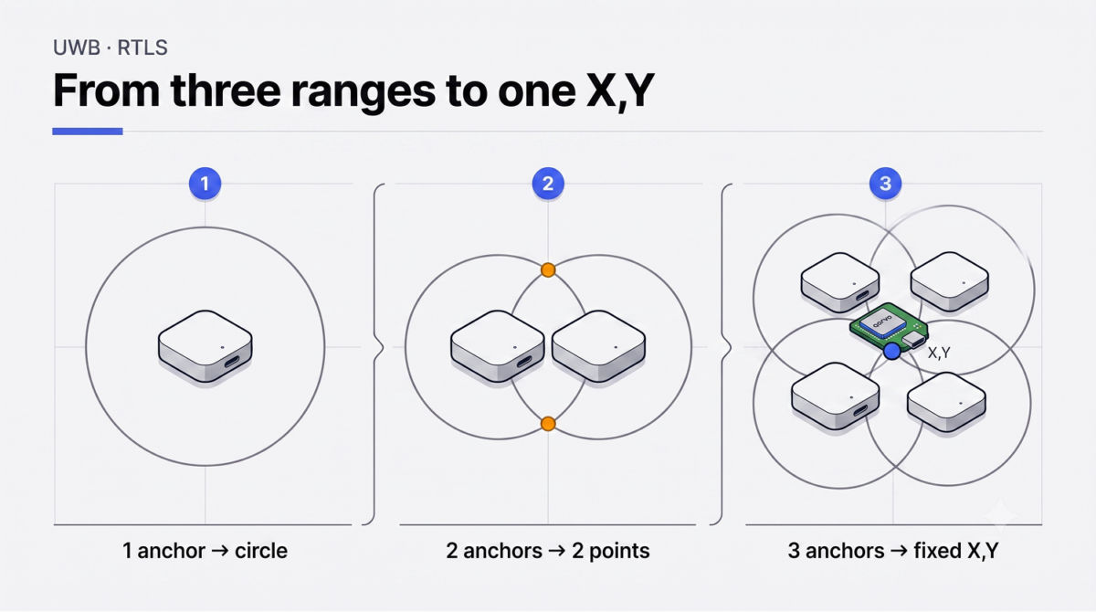
Here is the mechanism. One anchor and one tag give you a single range, say 4.2 meters.
That range draws a circle around the anchor, and the tag sits somewhere on it.
Add a second anchor and you get two circles that cross at two points. Add a third anchor and the three circles meet at one spot.
That spot is your X,Y, and on a DIY rig you compute it yourself, inside your own Arduino sketch,
straight from the raw ranges.
Two things bite people here.
First, antenna delay. Every UWB module adds a tiny, fixed timing offset before the signal actually leaves the antenna. Skip the correction and that offset turns into tens of centimeters of range error,
which then smears your computed position. You tune it per module, by hand, against a known distance.
Second, anchor coordinates. Trilateration only works if your code knows exactly where each anchor sits.
Measure those positions off by 10 cm and every tag reading inherits the mistake.
None of this is impossible. It is just work, and it is exactly the work the ranging tutorials skip.
The kit route removes the trilateration step. The GrowSpace developer tag runs trilateration on-device.
You send the `lep` command over serial and the tag replies with a finished coordinate string that starts with `POS,`. No trilateration code to write. You parse a comma-separated line and you hold X,Y.
How many anchors do I need for 2D positioning?
Three, at a minimum. Here is the full breakdown.
| Positioning goal | Anchors required | Update rate | Kit accuracy |
| Distance only | 1 | up to 10 Hz | 10-30 cm |
| 2D position (X, Y) | 3 or more | up to 10 Hz | 10-30 cm |
| 3D position (X, Y, Z) | 4 or mor | up to 10 Hz | 10-30 cm |
One anchor gives range. Two anchors leave you with two candidate points and no way to pick.
Three anchors pin down a single X,Y on a flat plane. Want height, Z, as well? Add a fourth anchor and
spread the four across different heights, because anchors mounted at one level cannot resolve vertical movement.
Keep anchors at least 2 meters apart. Indoors, hold the spacing under roughly 15 meters between
neighbors so the ranges stay clean.
Why does my UWB position keep jumping / fluctuating?
Three usual suspects: too few anchors, wrong anchor coordinates, or an obstacle in the signal path.
Too few anchors is the first thing to check. When a tag only sees two anchors at a given moment,
its position collapses or flips between candidate points. Walls, forklifts, and people all block UWB,
so an anchor you counted on paper may drop out in practice. More anchors, better spread, steadier fix.
Wrong coordinates are sneakier. Type an anchor position as 2.5 meters when it actually sits at 2.8, and the tag reports a confident, stable, wrong location. Re-measure.
Double-check the axis you keep getting backwards.
Obstacles are the third. Metal shelving and vehicle bodies reflect UWB pulses, and a reflected pulse arrives late, which inflates the range. This effect is multipath. On a plain DIY setup, multipath in a metal-heavy room can push error out to several meters.
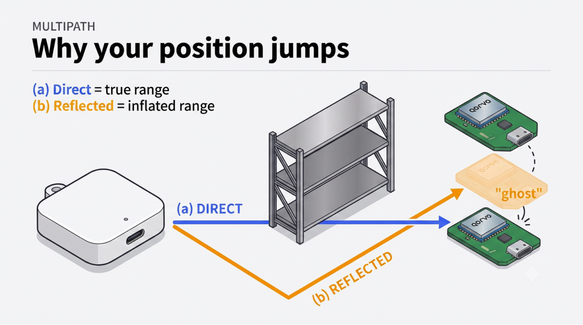
Here is where the hardware choice starts to matter. On a hand-built rig, those reflections wreck the reading and smear the computed position several meters wide. A field-tested system holds up. In one metal-dense automotive-logistics site, packed with thousands of vehicles, the platform held 23.05 cm in the field, a figure that came from a fused UWB plus RTK-GPS setup where the kit’s own standalone spec runs 10 to 30 cm. Metal is the test. The reflections that blow up a hobby build are exactly what field validation has to survive.
The same engine has cleared field trials at more than 40 industrial sites. Metal, dust, vibration, heat. The coordinate stream survives conditions that flatten a desk prototype.
How do I wire a UWB tag to an Arduino?
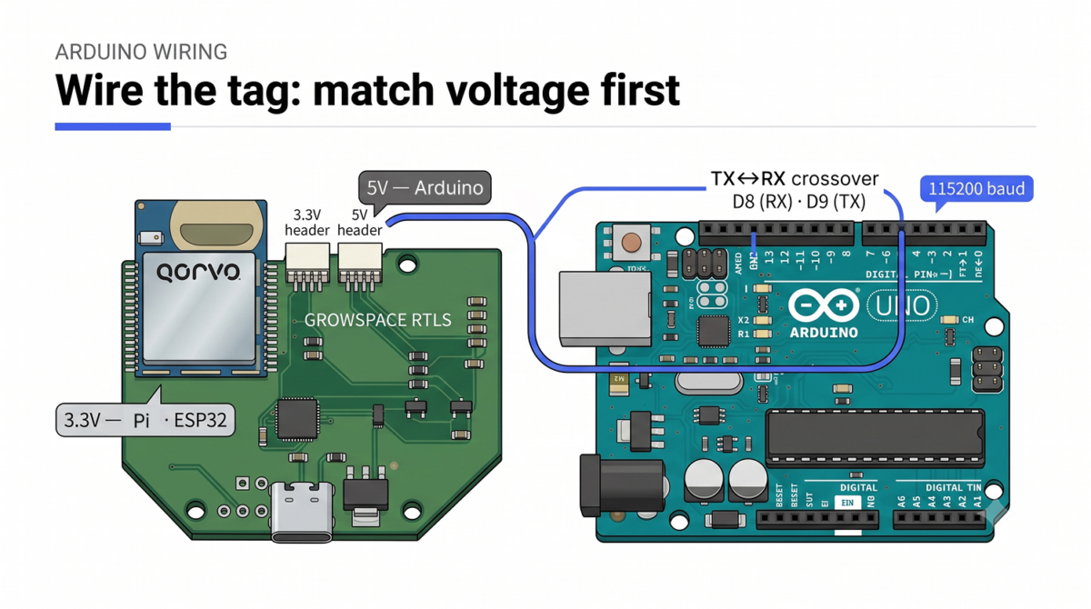
Use the tag’s right-side 5 V connector, cross TX to RX, and read it with AltSoftSerial on pins D8 and D9.
That is the whole wiring in one line. Now the details, because one of them can fry your board.
The developer tag carries two connectors, and they run at different voltages. The left connector is 3.3 V,
for Raspberry Pi and ESP32. The right connector is 5 V, for Arduino.
Wire an Arduino to the 3.3 V side, or a Pi’s GPIO to the 5 V side, and you can kill the circuit.
Match the voltage first, every time.
After voltage, mind the crossover. The tag’s TX goes to the Arduino’s RX, and
the tag’s RX goes to the Arduino’s TX. The two signals cross. Wire TX to TX and nothing talks.
The Arduino Uno has a catch. It carries only one hardware serial port, and the USB monitor already owns it.
So you route the tag through a software serial port instead, using the AltSoftSerial library on RX pin D8 and
TX pin D9. Need rock-solid serial at speed? Step up to a Mega, which gives you four hardware ports and
skips the software-serial fragility.
Set the link to 115200 baud, and send a carriage return with every command. Type `si` first. When the tag answers with its system info, your connection is live. The full pinout for every board sits in the [setup guide].
Here is the parse. The tag streams lines that start with `POS,` when you run `lep`, and lines that start with `DIST,` when you run `lec`. Split on commas and pull the fields you want.
// Reading lep output from a UWB developer tag

// Example line: POS,-3.41,9.54,-1.53,74

if (line.startsWith("POS,")) {

  int c1 = line.indexOf(',');

  int c2 = line.indexOf(',', c1 + 1);

  int c3 = line.indexOf(',', c2 + 1);

  float x = line.substring(c1 + 1, c2).toFloat();

  float y = line.substring(c2 + 1, c3).toFloat();

  // x, y come in meters. Plot them, log them, act on them.

}
That `74` at the end is the quality factor, a 0 to 100 confidence score. A reading of 60 to 80 or
higher counts as a solid fix. Watch it drop and you catch multipath happening in real time.
One caveat on the parse. The code above reads the developer tag connected directly, whose line is `POS,X,Y,Z,QF`, so X sits in the first field. Read the same stream through the listener instead and
the format shifts to `POS,temp tag no.,TAG ID,X,Y,Z,QF`, which pushes X to the third field.
Wire the listener and parse for the tag layout, and every coordinate lands in the wrong column.
DIY or kit: which path fits you?
Build it from parts when the learning is the point. Writing your own trilateration and tuning antenna delays teaches you UWB from the inside, and for a research sketch that runs on one desk, that time pays off.
Reach for a finished kit when coordinates are the point. When you need X,Y today, on a deadline,
in a room full of metal, hand-rolled trilateration turns into the one thing standing between you and a working demo.
The GrowSpace Creator Kit sits on the kit side. Three anchors, a developer tag, and a listener come in the box. The tag computes position on-device and hands you `POS,` strings over serial, so the trilateration you would otherwise write yourself already runs inside the hardware.
The listener plugs straight into a PC over USB and streams tag coordinates without any gateway,
which suits early testing well. The companion software, SpaceLite and SpaceLite Pro, is what plots those coordinates on a map, so you watch the data move instead of squinting at a raw serial log.
Movement replay over time and heatmaps live in GrowSpace’s monitoring software.
One honest note on setup. On this kit you enter anchor coordinates by hand, in millimeters,
with the `aps` command. You place the anchors, you measure, you type the numbers.
The kit skips the trilateration, not the anchor mapping.
FAQ
Yes, with three anchors and your own trilateration code. The Uno’s single hardware serial port pushes you onto AltSoftSerial at D8/D9, and a Mega makes life easier, but a basic 2D setup runs fine on the Uno.
Serial, over UART, at 115200 baud with a carriage return on every command. For a networked, multi-tag build you subscribe to the coordinate feed over MQTT through a gateway instead. Nothing extra to install either way; you read the stream directly.
The kit spec runs 10 to 30 cm. Real rooms full of metal and obstacles widen that on any UWB system, and careful anchor placement plus field-tested hardware are what fight it. Placement matters most.
Get coordinates faster
The DIY path is real, it works, and it will teach you plenty. But if you would rather skip writing the trilateration math yourself and just send one serial command to read back a finished X,Y coordinate while a deadline looms over a metal-filled room, the finished kit is the shortcut. That is the trade.
See the configuration and pricing on the product page: [GrowSpace Creator Kit].