
This guide covers a listener-based configuration.
If you’re using the Creator Expansion Kit or a gateway-based setup,
please also see the Gateway Configuration guide.
In This Guide
This guide explains how to configure the listener included with the GrowSpace Creator Kit Q1,
receive UWB tag position data, and check it in real time in the Web Console.
You can also set up floor-plan-based visualization afterward.
What Is a Listener?
A listener is a device that receives the position signal broadcast by a tag and forwards it to the system.
Data flows tag → listener → software (or a server), making it a core component for real-time position tracking and visualization.
Connecting the Listener and Confirming Detection
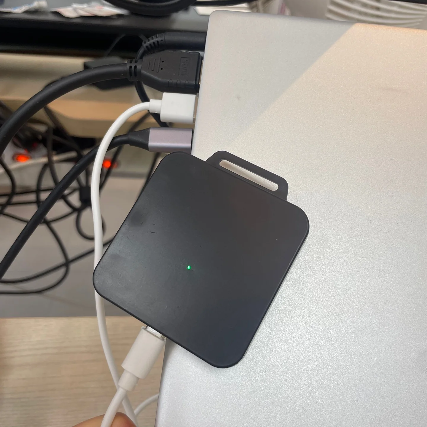
- Connect the listener to a USB port on your PC with a USB cable.
- Go to the Web Console.
You must use the Chrome browser. Other browsers may limit device connection or serial port detection.
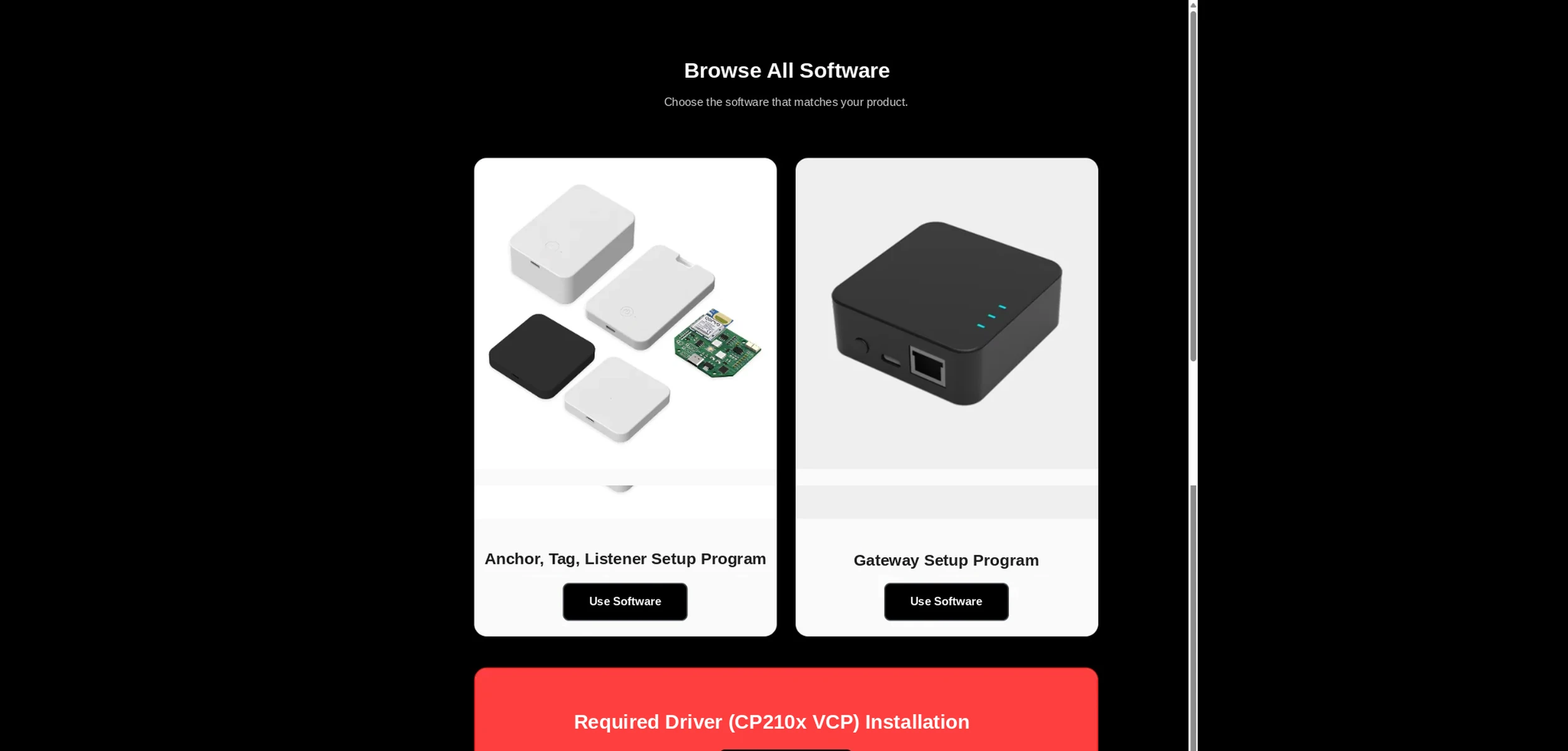
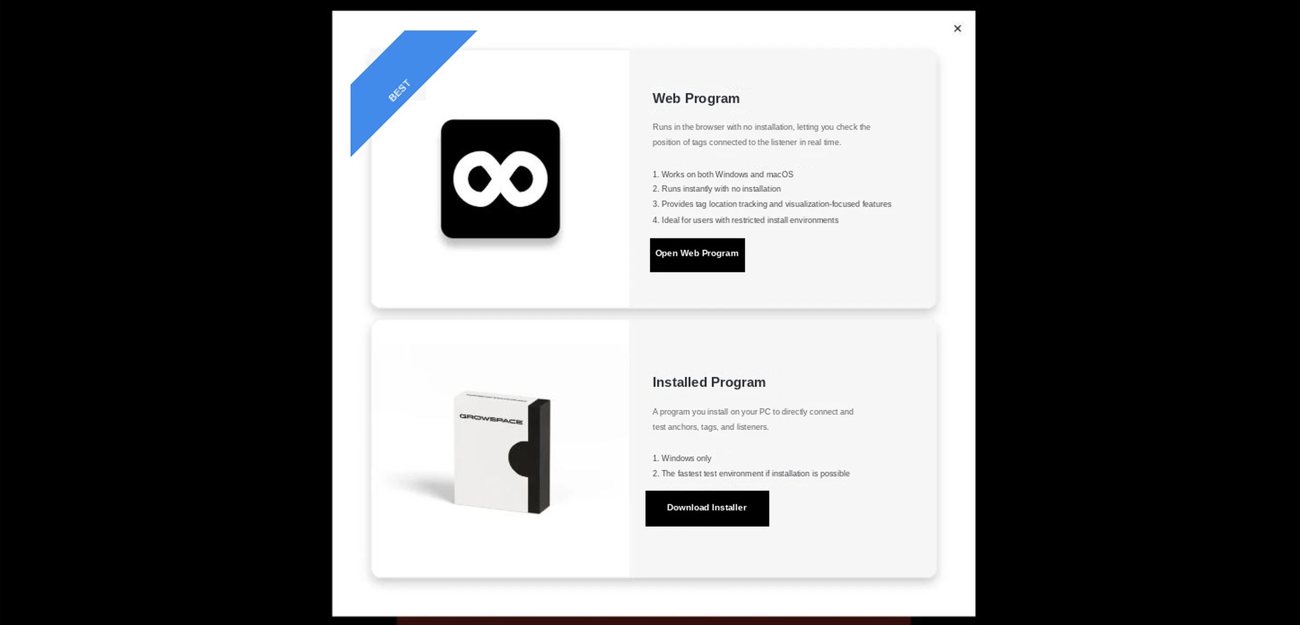
- In the left sidebar, click “Anchor / Tag / Listener Setup Program” → “Web Program.”
- The following setup screen appears.
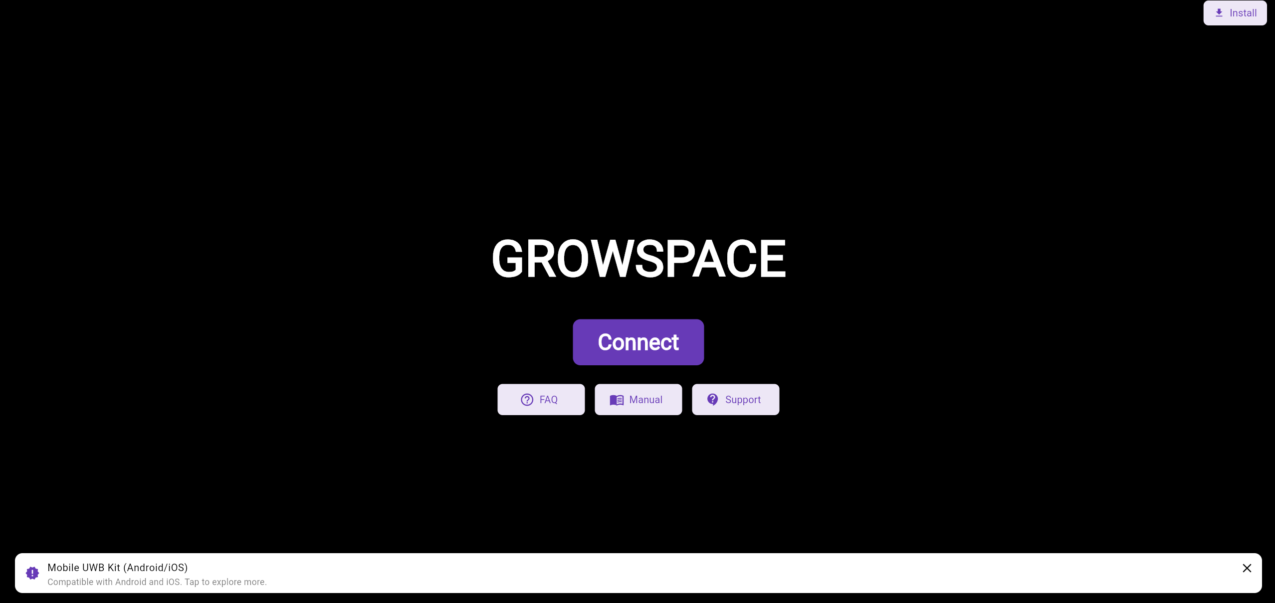
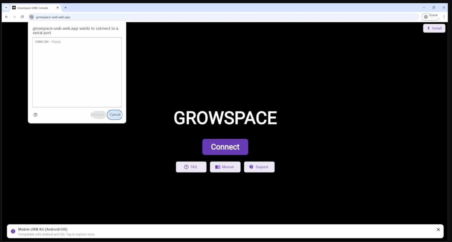
- Click the [Connect] button.
- Select the UWB listener from the list of available ports (COM ports).
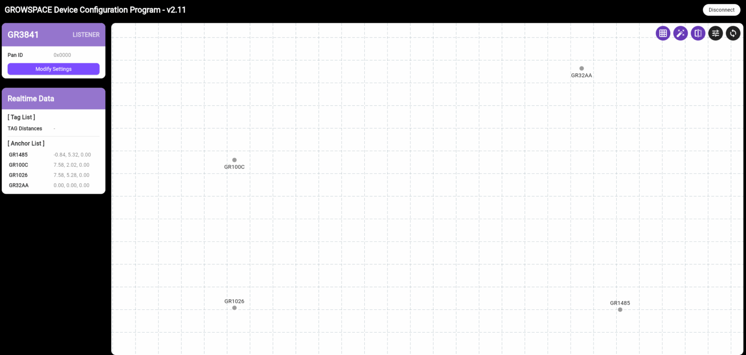
- Once connected, the following information appears on screen.
Top-left area (device info)
- Device ID: shows the unique name of the connected listener.
Example:GR3841 - Device type: shows as
LISTENER. - PAN ID: shows the currently configured network group ID.
Example:0x0000 - Modify Settings button: lets you edit values such as the PAN ID.
- Device ID: shows the unique name of the connected listener.
Bottom-left area (Realtime Data)
[Tag List]
- Currently connected tags, if any, are listed here.
- The
Tag Distancesarea shows the distance data the listener has received from tags.
→ This may be empty if no tag has connected yet.
[Anchor List]
- Lists information for every anchor connected to the system.
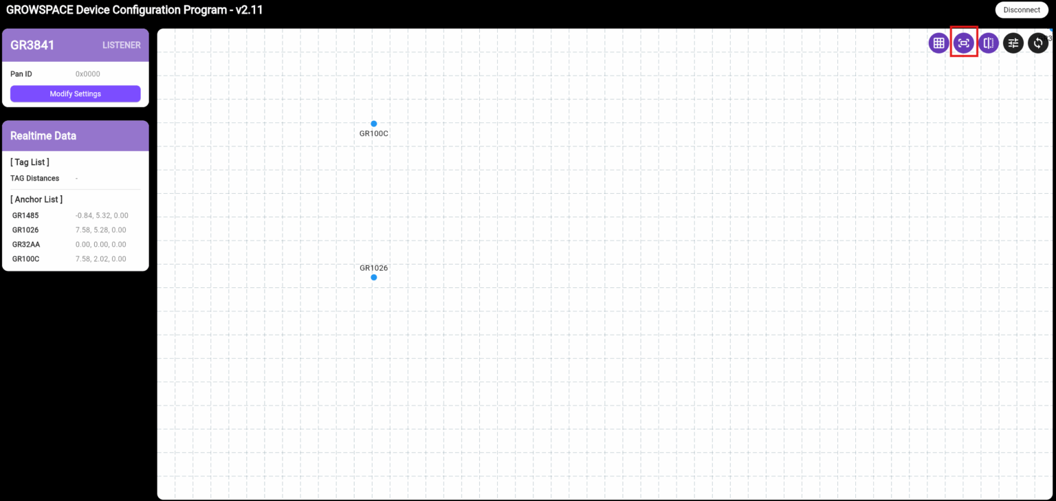
Center screen (position visualization canvas)
- Connected anchors appear as gray dots at their on-screen coordinates.
→ e.g.,GR100C,GR1026,GR32AA - Once a tag connects, it also appears as a red dot at the center, and a distance line is automatically drawn between the tag and each anchor the listener detects.
- Connected anchors appear as gray dots at their on-screen coordinates.
Setting the PAN ID
- Click [Modify Settings] to go to the settings screen.
- Enter the same value as the existing anchors/tags in the PAN ID field.
Example:0x0000
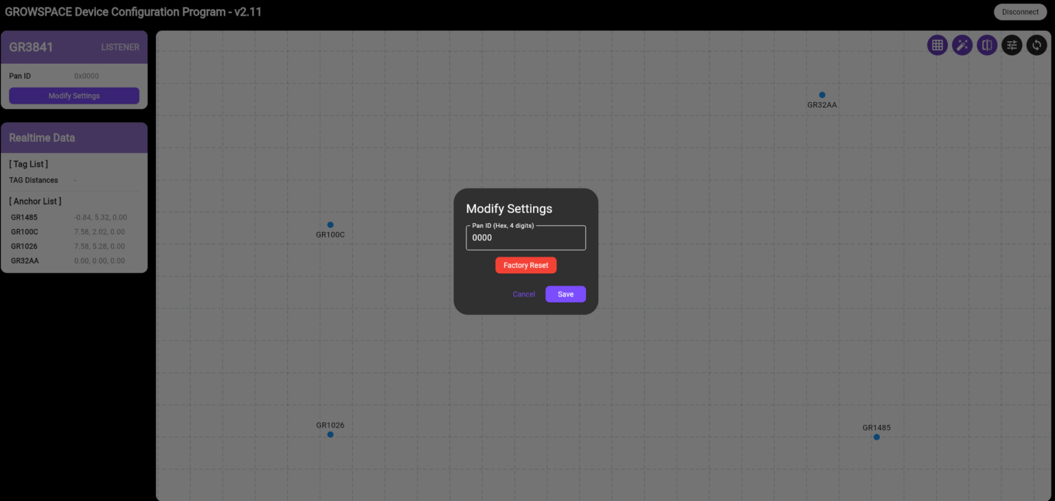
- Click [Save] to save it.
On a GrowSpace RTLS system, every device must use the same PAN ID for a tag’s position data to reach the listener correctly.
Setting Filter Strength
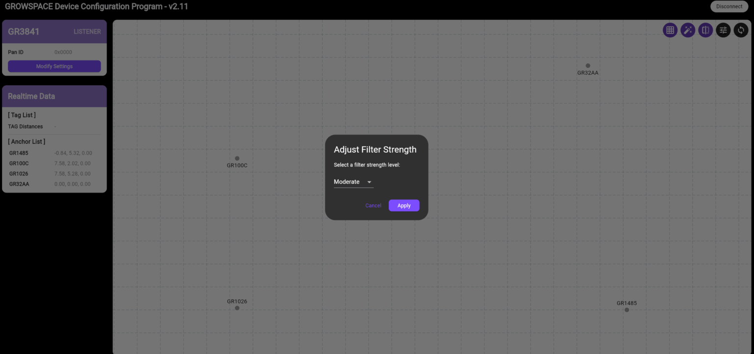
The GrowSpace Web Console lets you set a filter strength to smooth out the quality of position signals the listener receives for more stable results.
How to Set It
- Click the filter icon in the top right.
- Choose a filter strength from the 5 available options.
- Click [Apply] to save it.
| Option | Description | Recommended for |
|---|---|---|
| Very Strong | Strictly removes signal noise, almost no variation | Medical or safety-critical environments |
| Strong | Default recommended option, filters most jitter | General indoor position tracking |
| Moderate | Balances filtering and responsiveness | Development testing, prototyping |
| Soft | Fast response, some error | UX validation, prioritizing real-time response |
| No Filter | Outputs the raw signal as-is | Debugging, algorithm analysis |
If position readings jump or jitter frequently, we recommend
Strongor higher.
If you need faster responsiveness, trySoftorNo Filterinstead.
Floor Plan Integration
Uploading a floor plan image of your indoor space lets you visualize a tag’s position over the actual layout.
(A floor plan is optional — you can also operate purely on coordinates.)
Setup Steps
- Click the [Fit] button in the top right.
- Click [Manual Fit Settings] to enter manual alignment mode.
- Click [Upload Image] to upload a floor plan image (PNG, JPG, etc.).
Once the floor plan appears as the canvas background, manually align the actual anchor positions with their positions on the image.
A floor plan, site layout, or similar image showing the spatial structure works best.
Benefits of Floor Plan Integration
- Check tag positions on the floor plan in real time
- Intuitively analyze worker movement, space utilization, and inefficient areas
- Improve maintenance and operations through visualization
Setup Complete
If the listener is now receiving tag data correctly and the tag’s real-time position shows on the visualization screen, your setup is complete.
💻 A Desktop Installer Is Also Available
In addition to the Web Console, GrowSpace listeners can also be configured through a dedicated setup program (the GrowSpace configuration app). We recommend the installer for finer adjustments or for offline setup.
Installing the Setup Program
On your PC, go to https://drive.google.com/file/d/1L76hj_xsFe_flzxv6n_Svr73HJntvUxe/view?pli=1
Installer file:
uwb_settings.exe
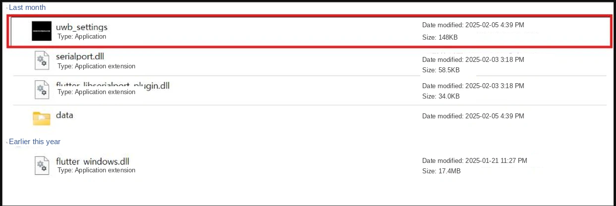
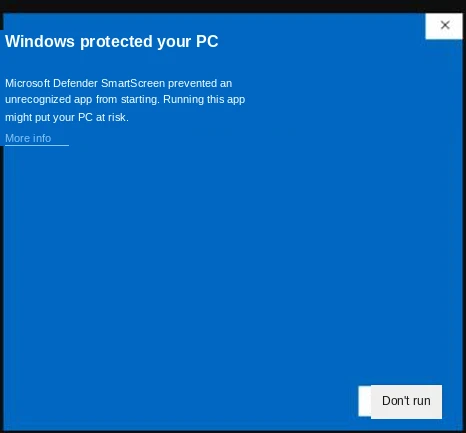
- If a security warning appears when running it, click [More info → Run anyway] to continue installation.
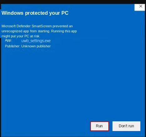
- Once installed, launching the program is all you need — you’re ready to go!
Connecting the Listener and Confirming Detection
- Connect the listener to your PC and launch the setup program (uwb_settings.exe).
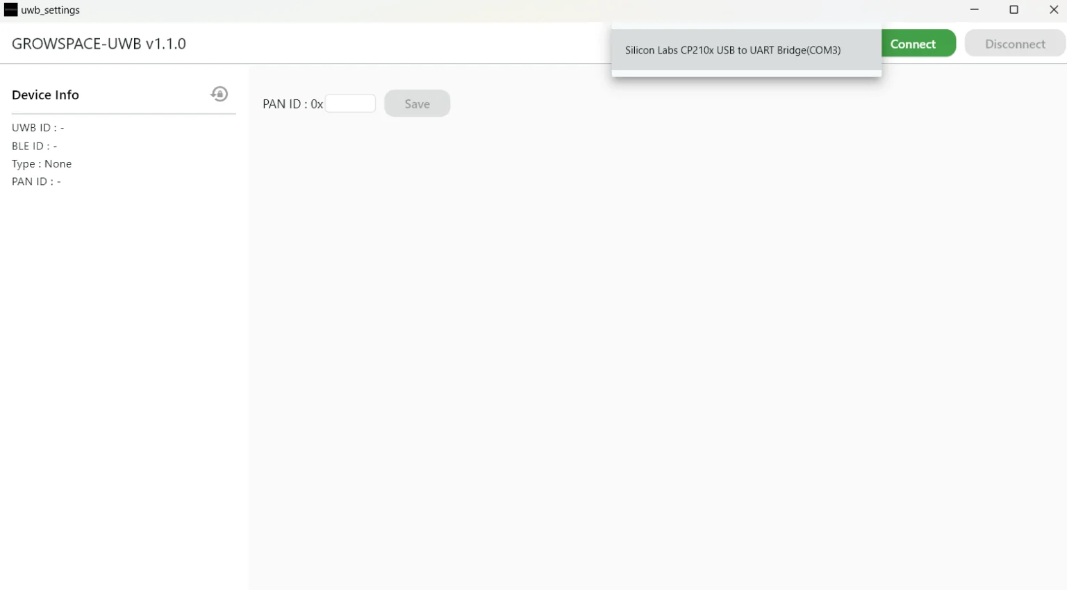
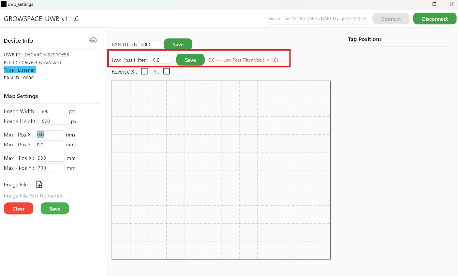
- After connecting, confirm the device shows Type: Listener in the
Device Infoarea at the top of the screen. - Find the Low Pass Filter field (located below the
PAN IDsetting). - Enter a filter value. (e.g.,
0.8)- Valid range: 0.0 or higher, less than 1.0
- An invalid entry shows a red warning message.
- Click [Save] on the right to save the setting.
Recommended Values
| Filter Coefficient | Description |
|---|---|
| 0.1 | Position changes are reflected instantly (faster response, more noise) |
| 0.9 | Reduces noise (slower position response, smoother movement) |
| 0.5 – 0.8 | Suitable for typical indoor environments (recommended range) |
Setting the value too low or too high can reduce position accuracy or responsiveness, so test to find the value that works best for your environment.